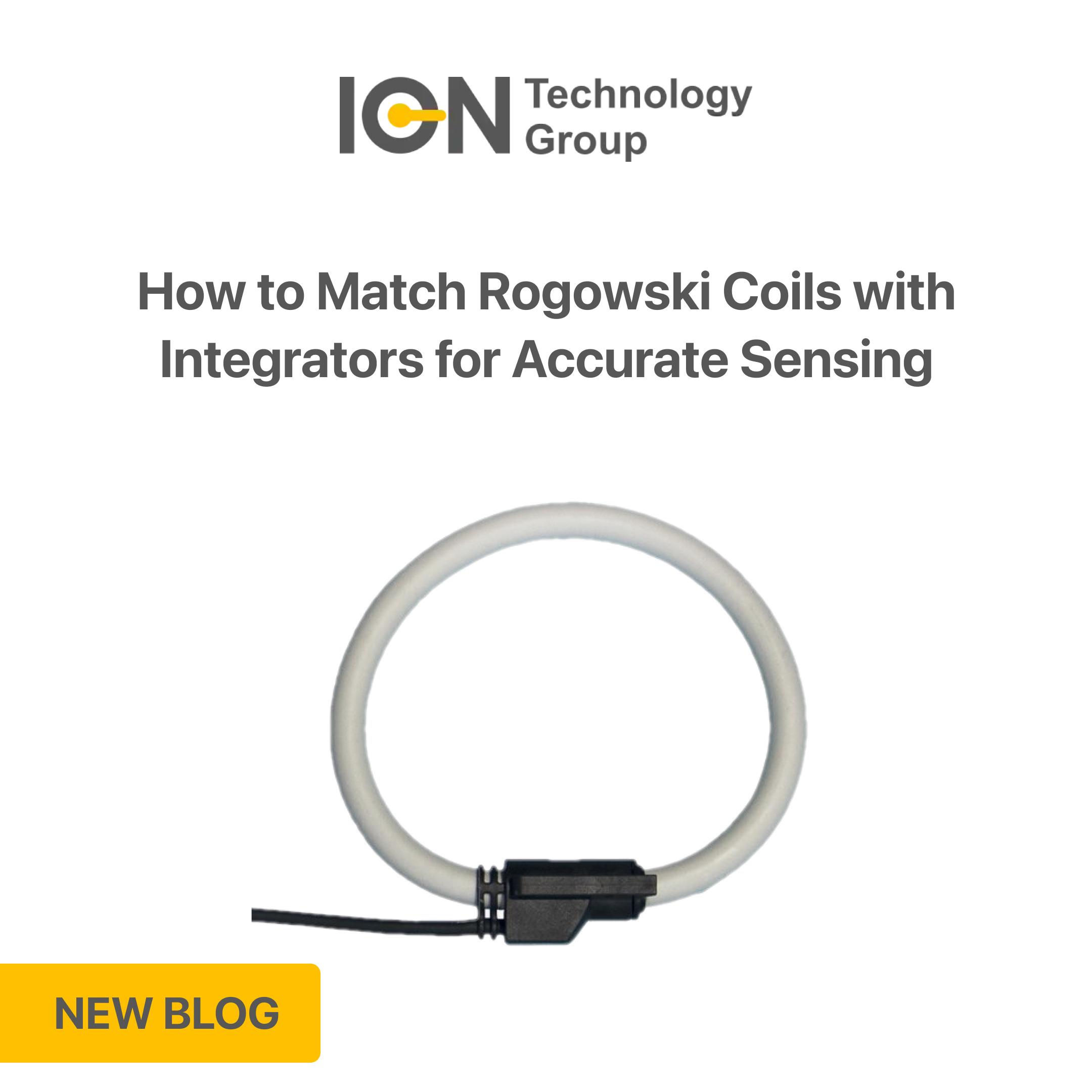
Flexible current loops have fundamentally changed the way industrial facilities and commercial infrastructure track electrical consumption. By allowing installers to wrap a flexible sensor around active three-phase busbars or tight cable bundles without disconnecting any primary wiring, project timelines are slashed.
However, achieving high-tier precision isn’t just about wrapping a coil around a copper bar. Because of the physics governing flexible sensors, a rogowski coil integrator is a mandatory component of the measurement loop. Without careful signal conditioning, the raw data generated by the field loop is completely incompatible with standard industrial power meters or automated PLC systems.
To ensure system-wide harmony and eliminate costly measurement errors, engineers must understand the technical rules of matching these two components for flexible current sensing.
The Underlying Physics: Why an Integrator is Mandatory
To understand why a matching rogowski coil integrator is vital, we must look at how the sensor functions. Unlike traditional current transformers (CTs) that rely on a magnetic core to produce a secondary current, a Rogowski sensor utilises a toroidal coil wound around a non-magnetic air core.
When an alternating current (I) passes through the centre of the loop, it induces a low-voltage AC output (V out). However, this voltage is not directly proportional to the current itself. Instead, it is proportional to the rate of change of the primary current over time (di/dt). The mathematical formula governing the raw output voltage is expressed as:
Where M is the mutual inductance of the coil. Because the raw voltage is a derivative signal, it exhibits two challenging characteristics:
- A 90° Phase Shift: The raw voltage output leads the actual primary current waveform by exactly 90°.
- Frequency Dependency: The output voltage scales linearly with frequency. A 100A current at 100Hz will produce twice the raw voltage of a 100A current at 50Hz.
The primary job of the integrator circuit is to perform mathematical integration on the raw voltage signal. This process shifts the phase back by 90° to align perfectly with the current waveform and neutralises the frequency dependency, creating a clean, proportional output that industrial systems can natively interpret.
Key Technical Criteria for Matching Systems
When configuring an architecture for flexible current sensing, pairing mismatched hardware can introduce significant reading errors. Engineers must verify three core parameters during the selection process:
- Phase Alignment and Power Factor Accuracy
Cheap or generic signal conditioners often introduce minor internal phase-angle errors during the mathematical integration process. While a phase error of just 0.5° or 1° sounds negligible, it has a devastating impact on power quality analysis.
In systems with a low power factor (such as uncorrected electric motor circuits or heavy inductive loads), minor phase displacement dramatically distorts calculation of kilowatts (kW) and reactive power (kVAr). High-performance, factory-matched systems ensure that the phase displacement remains virtually zero across the entire dynamic range.
- Input Impedance Matching
Every Rogowski coil has a specific internal resistance and inductance determined by its winding density and cable length. The input stage of the matching integrator must exhibit a highly precise input impedance. If the impedance is mismatched, signal attenuation occurs, or the system can pick up ambient electromagnetic interference (EMI) inside a crowded, high-voltage electrical enclosure.
- Output Standardisation for the Processing Architecture
Once the signal is integrated, it must be converted into a format that fits your downstream hardware. Modern architectures lean toward three main output types:
- Standard 0-333mV AC Loops: Ideal for modern high-density power meters, providing a safe alternative to traditional current loops.
- Traditional 1A or 5A AC Outputs: Designed to feed legacy power meters or protection relays without requiring a complete meter overhaul.
- Linear DC Analogue Loops (4-20mA or 0-10V): Perfect for routing data straight into a local PLC analogue input card for direct machine control.
The Power of Unified Hardware Integration
Specifying a factory-calibrated system, such as an Accuenergy Rogowski Integrator Kit (RIK), completely eliminates the engineering guesswork associated with multi-brand loops. When a coil and an integrator are designed together, the mutual inductance variables are pre-programmed into the integration firmware. This ensures true Class 0.5 or Class 1.0 measurement accuracy right across your three-phase network, from low-amperage baselines up to thousands of amps.
Furthermore, unified systems streamline commissioning. Instead of requiring tedious field calibrations with external variable signal generators, matched systems allow technicians to adjust current thresholds via straightforward on-board dip switches or native software interfaces, speeding up installation times significantly.
Summary Checklist for Systems Integrators
Before deploying hardware into an active commercial solar grid or manufacturing plant, ensure your measurement loop satisfies the following parameters:
Selection Parameter | Engineering Goal |
Phase Shift | Must be < 0.5 degrees to preserve strict Power Factor and kW calculations. |
Dynamic Sensitivity | Constant linearity from 10A up to the maximum rated breaker limit |
Scaling Adjustability | Selectable primary amp settings (e.g., 500A to 5000A) for multi-site utility. |
Enclosure Integration | Standard 35mm DIN-rail mounting with low thermal output inside sealed panels. |
By ensuring your flexible sensors and signal processing units operate in complete harmony, you safeguard your sub-metering data from drift and noise, delivering rock-solid energy analytics from the switchboard copper straight to your automated control network.
Ready to deploy a high-accuracy current tracking system without causing plant downtime? Reach out to us today!